BEAM Robotics- based on Nervous Network Technology
Experiments into colour visoooo00000000000OOOOOOOOOOOON!!!
|
BEAM Robotics- based on Nervous Network Technology
Experiments into colour visoooo00000000000OOOOOOOOOOOON!!!
|
|
COLOUR VISION: ELECTRONICS
Lets build a Spectral Processor!!!
SPECTRAL PREPROCESSING
We managed to figure out that in order to sense the light we need a sensor of some sort.. These can be one of: the following
LDRs
Photodiodes
LEDs
Special Application Packages
LDRs
~are nice to use because they are pretty damn cheap and tiny. Also I believe you can buy them according to resistance range and perhaps even spectral response.
Photodiodes
~are great to use too, as you can buy them according to just about any parameter one an think of. Spectral response of course is an option
LEDs
~ as in plain old LEDs with coloured cases can be used as well. "How, sir?" It's simple really, LEDs have a spectral response to the same frequency of light they emit. You can use LEDs to sense things. Just take an LED and hold it close to an incandescent bulb and read the voltage from it.
Special Application Packages
Now as one could expect there exist sensors made to
specifically sense coloured light. Some are claimed to be as good as the
human eye in identification of colours. Some even have built in
amplifiers and such. Unfortunately these packages can be expensive and
unless you get a bunch of free samples I would not catch myself fooling
around with them. Imagine connecting your nifty expensive sensor
backwards are to too high a supply.
Anyways it would be nice to be cheap.
From the little notes on the sensor choices a few things
become apparent. The first of which is the need for coloured
filters.gels in order to allow certain packages to only respond to a
particular frequency. This is certainly the case with LDRs and perhaps
even photodiodes.
LEDs and special application packages would not have a need for filters,
as in one case they device is designed for one frequency only and the
other has a built in filter by nature of its colour.
However, all of the above will need to have a filter for IR light.
I decided to experiment with LEDs and LDRs to see which is best.
LED DETECTOR
The choice of using an LED was pretty clear [get it, you know, clear LEDs ]. They have built in filters, are sensitive to the light which they emit, cheap etc.
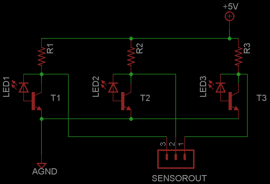 The circuit to the left is what I hope will do the trick. The LED and
transistor pair make for a phototransistor. In addition, the transistor
is set up as a variable resistor. All in all it should function as an
LDR with a built in filter.
The circuit to the left is what I hope will do the trick. The LED and
transistor pair make for a phototransistor. In addition, the transistor
is set up as a variable resistor. All in all it should function as an
LDR with a built in filter.
Each of the LED's colours will correspond to that of
either Red, Blue and Green [yellow].
In addition one may wish to include a sensor to detect ambient white
light, or ambient infrared or whatever other environmental factors that
may affect the readings.
A point to note in the use of the LEDs is that instead of using coloured LEDs one may use the water clear types. I am not sure if the ones with coloured cases actually have an emitting element which produces the respective colour or not. As such, this is an area open for experimentation.
SPECTRAL COMPARATOR
The spectral Comparator is the circuit which reads the output from the LED DETECTOR and makes some sort of sense of it. Provision is made in the circuit for the addition o the ambient detector, although one manifesting itself in another form may be more effective.
Note: I started on this circuit and then found this one online. It was done by Wilf Rigter and I adapted mine to suit. So the result is what you see below.
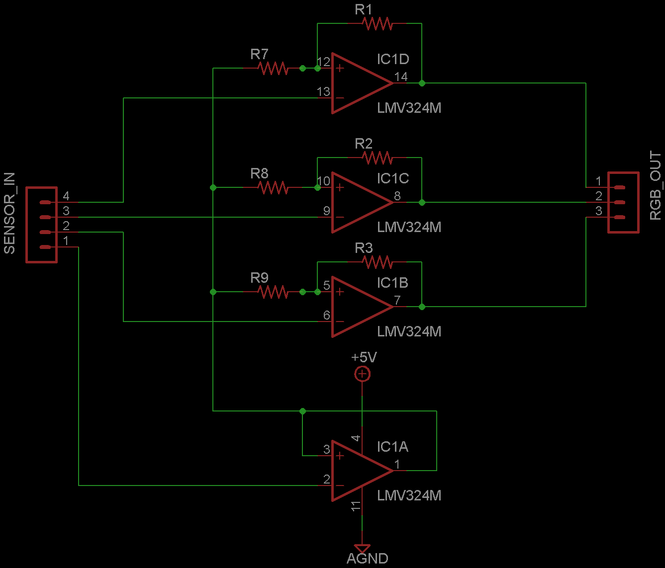
Basically it's just op amps, nothing too fancy. It uses the LMV324 which is a low power quad op amp.
In the schematic, IC1A is used for the ambient
condition. Depending on how things go this may be used to detect ambient
IR. Contrast this to the schematic in the link above.
Another thing I might add about the Spectral Comparator is that it may
no be all that necessary in the end. If the LED DETECTOR can distinguish
colours on its own there might not be a need for this circuit.
On the note of cleaning things up, one may have to add 1K-5K pull up
resistors with diodes to the outputs of the op amps.
Also there is no provision for adjusting sensor sensitivity, but that
would be simple by putting 20k or so variable resistors on each of the
SENSOR_IN lines, tying the RGB pots together and placing a diode between
them and the 20K pot for the ambient sensor.
The Spectral Comparator should return outputs for RGB
detected. Currently I am only interested in those values, and do not
have much interest in decoding the secondary colours, but one may use
the decoder found in the link above for that purpose I suppose.
It is more important in my opinion to have an accurate Primary sensing
before tackling the decoding of multiple secondaries and hues.
|
From this treatment we can realise what he requirements are for this experiment. Click to see what they are.
|