BEAM Robotics- based on Nervous Network Technology
| Nv Neuron | ||||||
|
BEAM is based on nervous networks. The basic element of a nervous network is the neuron. BEAM tech
makes use of several types of neuron, the most basic of which is the Nv motor neuron.
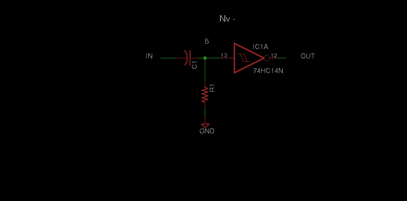
It consists of an inverter, and an RC differentiator circuit. Specifically, a capacitive input and a resistor
reference tied to either GND or VCC.
The Nv responds to sudden changes at its input. This is due to the capacitor.
The most common use of an Nv neuron is to
delay the propagation of a signal.
Also, the Nv uses negative logic, so an active neuron will have a output of 0v [low].
As it has an RC circuit, it has a time constant, T [tau]:
There are 2 types of Nv neuron, a +ve Nv
and a -ve Nv. This is based on
if the resistor is tied to VCC or GND. I will not describe the circuit, as there are several
You can read more about the Nv neuron at:
Beam Wiki
|
Solarbotics Encyclobeamia
|
Wilf's Article [recommended]
|
These neurons are usually interconnected in arrangements called nervous networks. There are several topologies used in constructing Nv networks. These are chains, branches and loops. Loops, and most non branched topologies are called n-cores, where n is a prefix denoting the number of neurons in the core. Bi, tri, quad, etc. Once upon a time, the quadcore, or microcore[old], was the most common topology, but now the bicore, or unicore[old] is the most commonly used controller. Pulses travel throught these networks, and are used to control various other actuatiors, circuits, etc. The Nv network can be said to be the brains of the bot, but it functions akin to the periphery nervous system of animals. In addition to being delayed, the pulses traveling though the network can be augmented by the sensory data. This can generate signals which are sent to the actuators. This creates a feedback loop. Indeed, this shows the versatillity of the Nv controller for use in processing signals. This brings us to the next section, namely methods for influencing the pulses. |
||||||
| Parameterized Nv Neuron | |||||
|
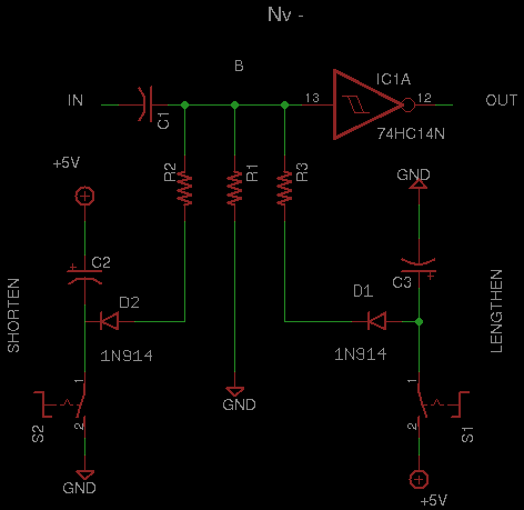
The Nv neuron has several parameters which control it's pulse durations\:
By varying any one or any combination of these parameters, we can manipulate the Nv. Shown below is an Nv with circuitry for changing the resistor parameters. One circuit when activated will shorten the Nv pulse duration, while the other will lengthen it. In addition, the capacitor in the circuits [C2 & C3] will keep this parameter active for a period of time. It is also possible to influence the pulse duration of the Nv by using different capacitors at [C1] , but in general, the cost of a resistor remains the same regardless of the magnitude of resistance [cost inc with watts], whereas the cost of a capacitor increases with capacitance.
From this basis, it is a very simple matter to input any form of sensor data into the Nv, causing it to
alter it's pulse duration in response. We can either shorten or lengthen the pulse. An example of this would
be in controlling a motor. A minimum of 2 Nvs are required to control a DC motor. Each Nv explicitly controls
the motor's rotation in one direction. Now, in this standard configuration, the motor's output shaft will
rotate by equal amounts if the T of the neurons are the same. What do we do if we wanted to turn the shaft
more CCW, than CW? Simple. We can lengthen the pulse duration of the Nv responsible for CCW rotation. Or, we could
shorten the pulse duration of the Nv responsible for Clock Wise roation. The latter is useful if the shaft
has limits on its rotation. Also, both shcemes could be employed at once.
So, for any of the n resistors in use, we get a new
T.
|
|||||
| Argument Net | |||||||
|
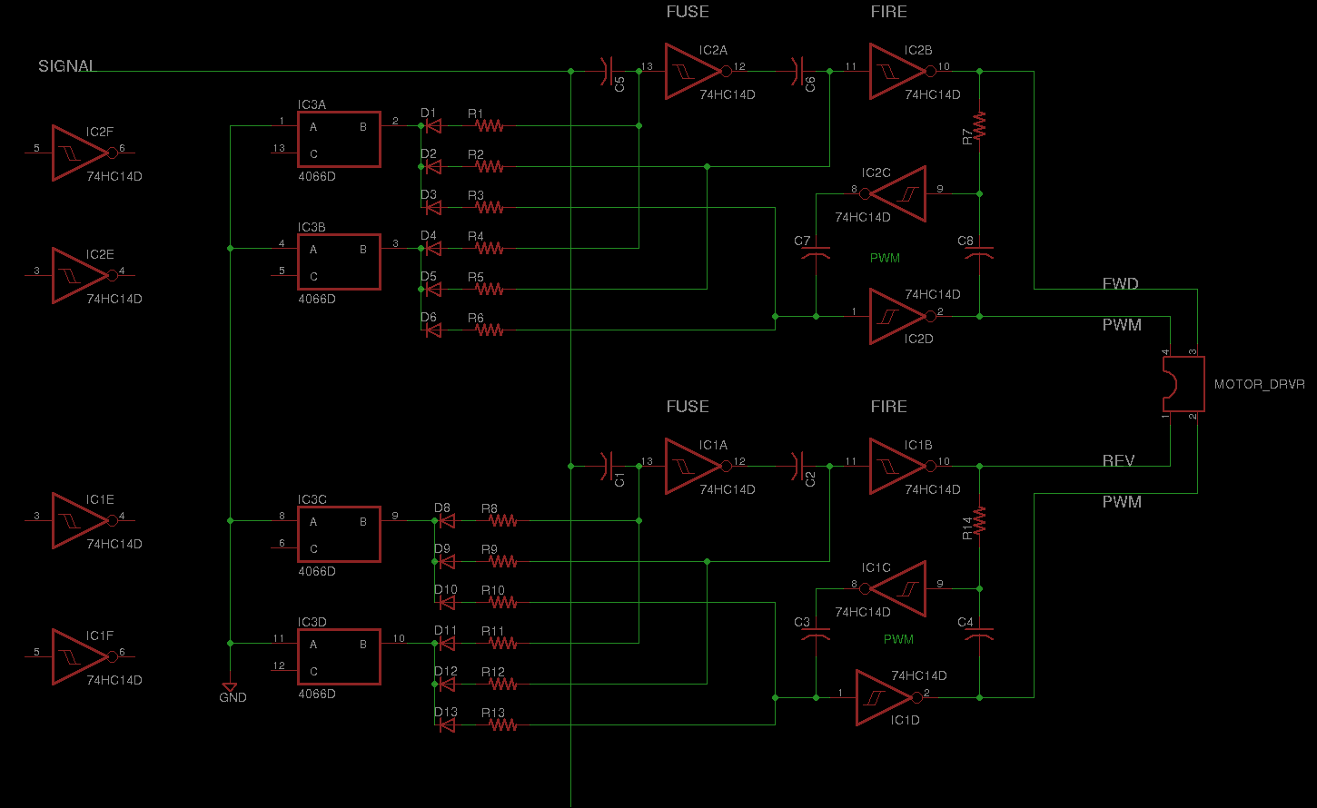
This is an offshoot of the Paramterized Neuron.
Note that ANY neuron is the fuse
for the proceeding neuron in the chain, in
any network.
So one does not explicitly need add in a single neuron to each of the firing ones, although, the a separate
fuse neuron could be useful for processing sensory information for the fire neuron. This could be in the form of
shortening or lengthening the fuse, ie, the pulse duration of the fuse neuron, via the scheme shown above. If the same
shortening/lengthening of the pulse duration is applied to the fire, this would be able to asjust the pulse duration
on the fly of the action.
The most remarkable aspect about this scheme, is that by placing several A-net chains, soley in parallel, it would be
possible to simulate/create ANY configuration of ANY core Nv network, simply by changing the resistance parameters.
To make a standard Nv chain of n neurons, n A-nets would be connected in parallel, such that the all receive the same
input pulse. The resistors of each of the fuse neurons would each be sequentially of a higher resistance. So when the
input pulse is supplied, the first A-net fuse times out, then the fire activates. The second A-net fuse would time out,
causing the respective fire neuron to activate. This would continue to the nth A-net.
|
|||||||


| Nv Nets | |||||||||||||||||||
|
A single Nv neuron on it's own isn't too useful for the overall control of a robot. You could probably turn it into
a standard schmitt oscillator then you could blink an LED for a beacon or sometihng.
Indeed, Nvs are the most useful when they are connected in networks.
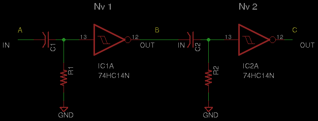
The simplest network consists of 2 neurons, and it can only either be a chain or a loop. In addition, 2 neurons are
the minimum nuber required to control a DC motor, as stated above.
In a basic 2 Nv chain, such as the A-net above, the output of the first Nv is connected to the input of the second.
Each of the resistors are referenced to ground.
The circuit diagram of the net will give you the assembly instructions. A
Biomorphic Map of the
Nervous Network is a graphical representation which shows how the
Nervous Net functions .
|
|||||||||||||||||||


| Gaits & Things | ||||||
|
Nvs in my book are mainly motor neurons. Their use is to control motors, or actuators in general. The current Nv net designs floating around, have most if not all of their Nvs dedicated to the control of motors. It is possible to tailor an Nv net to produce a specific pattern, to move a set of motors in a specific way, ie you can build a net to precisely match a specific gait.
... ... ... ... |
||||||
| Hexapod | ||||||
|
...
... ... ... ... |
||||||