BEAM Robotics- based on Nervous Network Technology


Spyder shares the name of Mark Tilden's orignal Vbug 1.1 Spyder, but the similarites end there. This robot uses a different Nv net, has different behaviours, sensors...
  Spyder  

MECHANICAL DESIGN

Spyder was a quadruped, each leg having 2 motors, presumably for lift and yaw. In addition, the legs each consisted of a 4-bar linkage, a system used for lifting the foot
bit, and several springs placed in key areas. An oddity of the mechanics, is that Spyder actually lowers the linkage to raise it's foot, and that the foot moves down as the
linkage moves up. The robot was actuated by pager motors mated to OTUs, and is described as such herein because they are 2 separate things. An OTU is not
manufactured with a pager motor neatly attached to it. Also, note that Spyder isn't symmetrical, Tilden built it this way because I think he claimed the world isn't
symmetrical, so it will adapt better. I like the whole bilateral symmetry of life, so I say the reconstruction will be symmetrical. This has the added benefit of
reducing the difficulty of working out timings for a symmetricalnet in an unsymmetrical robot.

LEGS

MECHANICAL DIAGRAMS

There were no exacting Diagrams of Spyder's leg mechanics, save for the photographs of the robot. The ones taken by Dave at Solarboticsprovide the best and most intimate detai ls of the workings.
In addition, recently Bruce Robinson emailed 4 drawings he had made in 2001 of Spyder's leg. These drawings are to scale, and one is a working diagram which contains dimensions.
The other 3 show various leg positions.
Simply, the leg consists of a 4-bar linkage, which can be modeled with popsicle sticks or strips of card:
" The 4 bar linkage is simple as well. Get 3 popsicle sticks and 4 thumb tacks, break one stick in half and then make a rectangle with the sticks.
Press the thumbtacks through the ends, joining them together. Hold one end of the rectangle at the centre of the stick, and simply move the other end up and down.
You'll find it will rotate, keeping opposite sticks parallel through the range of motion."

BRUCE'S DIAGRAMS

Spyder Leg | Scale Spyder Leg | Raised Spyder Leg | Neutral Spyder Leg | Lowered
Spyder_geometry-1.gif Spyder_leg-2.gif Spyder_leg-0.gif Spyder_leg-.gif

From Bruce's position Diagrams, we clearly see the oddity of the leg mechanics, in which the linkage is lowered to raise the foot. This is due to the fact that the OTU itself forms a bar of the 4 bar linkage, and the foot is connected to the OTU's casing. In addition, since the OTU is a bar, as it moves it will rotate a little. The spring attached
to the OTU and the opposite bar is used as a centering spring .
Note also, that the 4-bar linkage consists not only of 4 bars, but 4 pivots, and in Spyder, the lower pivot of the OTU is actually the motor output shaft, and the lower bar of the
4 bar linkage is soldered to the output shaft. It is this which causes the unique motion of the leg. (We can change to a conventional motion, ie, raising the linkage raises the leg, by simply swapping the system around, ie,
the motor end is connected to the yaw structures, and the foot becomes a bar of the linkage on the other end? "I haven't checked this)

AMIT'S DIAGRAMS

Spyder Leg | Original Spyder Leg | Original Spyder Leg | Experimental
IMG_3182.JPG IMG_3183.JPG IMG_3184.JPG

Download the pics, they are hi-res and easier to read under magnification. I've terrible writing. The first diagram is essentially the same layout as Spyder, with some cosmetic changes and as OTUs were not available,
different gear motors were drawn in. I also labeled 2 different leg attachment points. The original
is of interest here, the new attachment point is for a completely different purpose altogether, so just ignore it. The second drawing is an attempt to change the motion and function of the leg, such that when the leg is raised, the foot is raised as well. It is more complex than the original 4-bar linkage, but it's purpose is different.The original Spyder leg more so extends than lifts, this is good for walking, as the foot can be slid over the ground and the bot will not teeter, however, this design does not appear to be capable of climbing, or lifting the limb over an obstacle. The new one can (I think).By far the simplest leg design would be to eliminate the 4 bar linkage altogether, and simply make a leg by soldering a bar to the output shaft of the yaw motor, and to that attaching the pitch motor, and then soldering the foot to the output shaft of the pitch motor. Then the leg can be used for most any gait, as long as the correct motor timing is found for that gait.


SEMI-RIGID LINKAGE

You can attach the brass tubes directly to the motor shafts and omit the springs. Not a problem there. The spring in the brass tube is a normally compressed spring,( you pull it, it extends, release it and it contracts again). Now one end of the spring is connected to the motor output shaft, the whole thing placed inside the brass tube and the other end of the spring is connected to the end of the tube.The end of the brass tube housing the spring is soldered to the respective partof the linkage.The one for the yaw motion is connected to the 4-bar linkage , and there is another spring thing in the lower link of the 4-bar linkage as well. If you look carefully, the fixed end(where the spring is soldered to the tube) is also soldered to a length of thick wire. Together these make up the entire lower linkage. You can see this in the hi-res pics. Altogether, it creates a flexible linkage under certain conditions. In normal operation, the spring remains within the tube and acts as a solid linkage. In fact,depending on how far the spring is retracted within the brass tube, the force is directed along the brass tube rather than
the spring. But when the legs are overdriven as you said, the spring extends out of the brass tube allowing the leg portion to flex (due to geometry of the 4-bar linkage). The brass tubes are necessary, because in practice,
the springs won't be in line with the to the linear action of the force from motors(through the 4-bar linkage really), well, unless you solder really well and set up everything very square. When the motor moves, it might just cause the spring to deform by bending, and the spring won't work as a solid linkage. The brass tube is part of the solid linkage and a guide for the spring.
The arrangement allows one degree of freedom for the spring to operate. (static in all other axis.)

MOTORS

This robot used 8 (Namiki?) pager motors.These were mated to the OTU geared stage. One could use any geared motor, but changes would have to be made at least to the 4-bar linkage system. The leg mechanics sketches above show such a change.

GEARED STAGE

Spyder uses 8 OTUs as the geared stage of its motors. They are a gearset which one can salvage from analogue stove timers, electric analogue clocks, dishwashers, and old washing machines.

This link at Solarbotics : | Solarbotics Oven Timer Unit Modification | gives all of the information necessary to repurpose OTUs for use in a robot.

The yaw motors on Spyder are placed at an angle to its body. The OTUs are mounted with positive camber angles, with respect to the left and right sides of the frame. So the OTU's on the lateral sides point outwards from their respective sides . In addition, fore and aft motors are also slightly angled such that their output shafts point in their respective directions of fore or aft.

... ...
.png .png

CHASSIS FRAME

Spyder is built around a square wire frame. Each of the yaw OTUs are soldered to this square's vertices. The battery is placed in the middle of this frame and a spring stretched between two sides holds it in place. Other wire sub frames are soldered to this, these include:
a frame is soldered to a side of the main one, which is shaped to hold the ribbon cable socket and Spyder's eyes. Another small rectangular sub frame is soldered to one of the lateral sides of the main frame and an OTU and is large enough to enclose a DC female charging jack. OTUs on what is to be the left and right sides of the robot have a wire soldered between them. I cannot determine if other sub-frames exist.

REPLICA FRAME

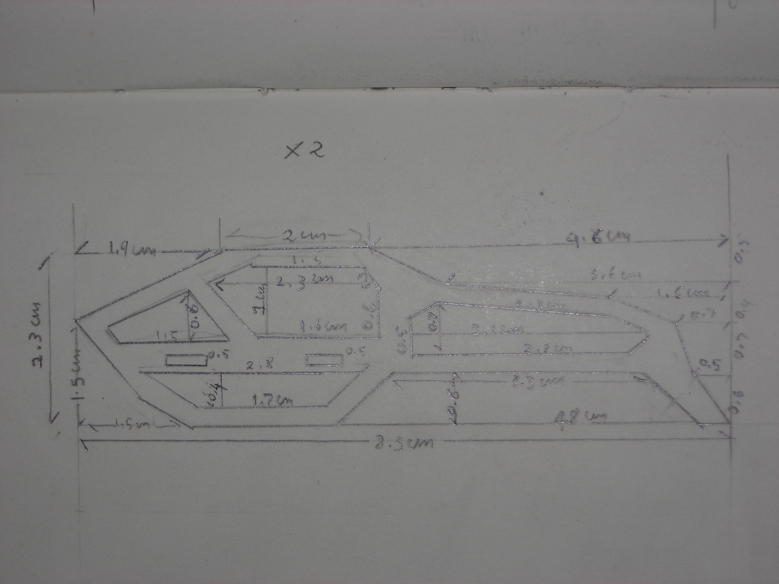
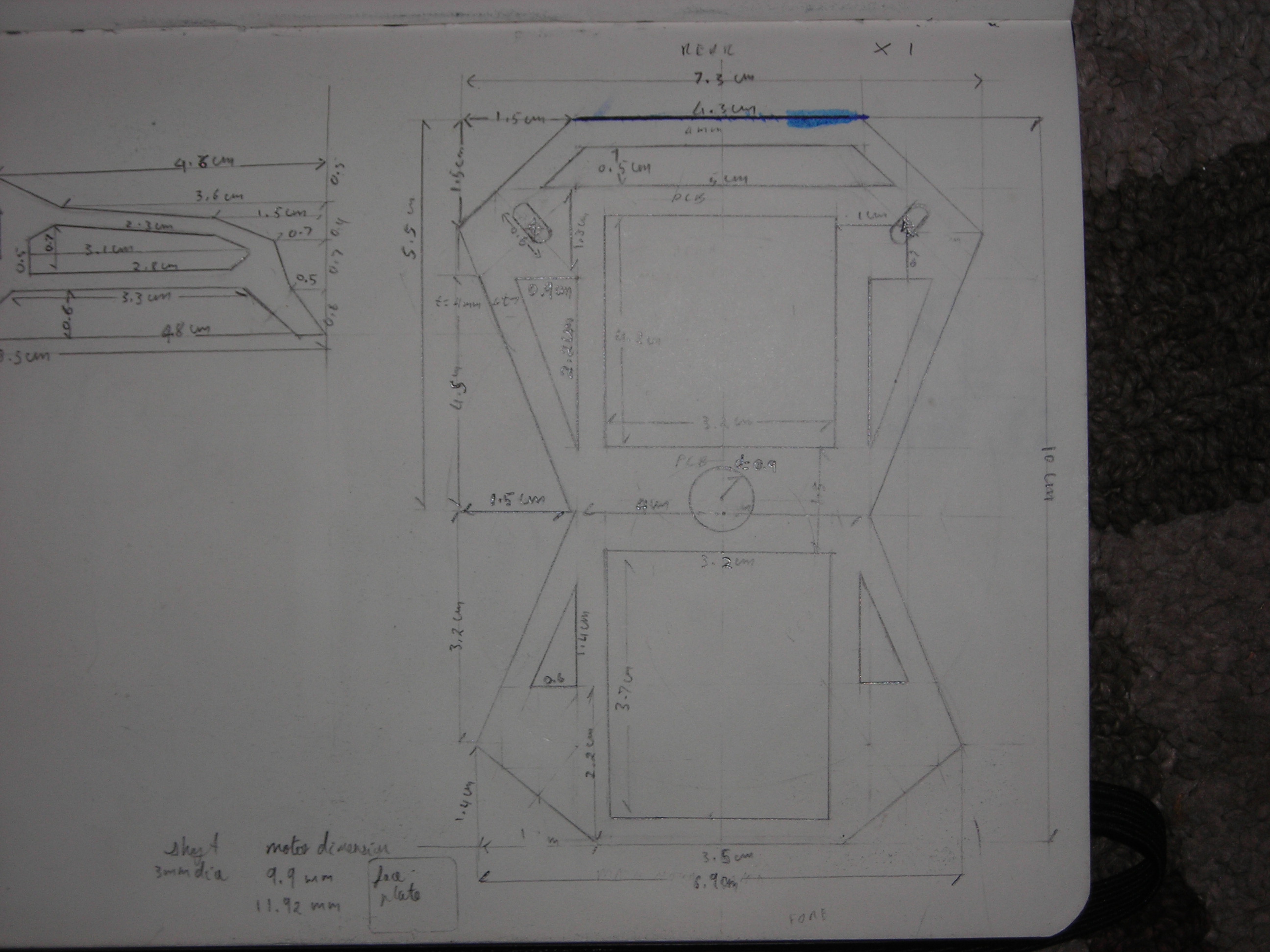
A frame will be built from double-sided fibre glass PCB. It will have a simple geometrical shape, and will use mortis and tenon locking systems to join structural parts together. In addition, because the board is copper clad, the joints may be soldered in place. This means that the frame is both strong, and light. Furthermore, the inner area of the frame can be filled with another pcb of similar dimension, [tesselation] . This board will have some of the robot's electronics.

Replica Frame Replica Frame
DSCN4672.JPG DSCN4675.JPG

Frame sketches & CAD files: | Scale drawings,pdf(2010/08/12) | AUTOCAD DWG |


...