BEAM Robotics- based on Nervous Network Technology


Spyder shares the name of Mark Tilden's orignal Vbug 1.1 Spyder, but the similarites end there. This robot uses a different Nv net, has different behaviours, sensors...
  Spyder  

MECHANICAL DESIGN

Spyder had 8 DC gear motors, made from a pager motor and an OTU. The replica shall use Solarobtics GM12As.
The motors accept signals from the control circuitry and turn in response, however, the output of the control circuitry may be in the order of 10mA, and the GM12As require around 30-456mA. To supply the needed current, a motor driver is used. | Motor Drivers on Beam Wiki |

The orginal Spyder used (I think) a basic 74AC245 driver. Info on those can be found at: | 74*245-based Motor Driver |
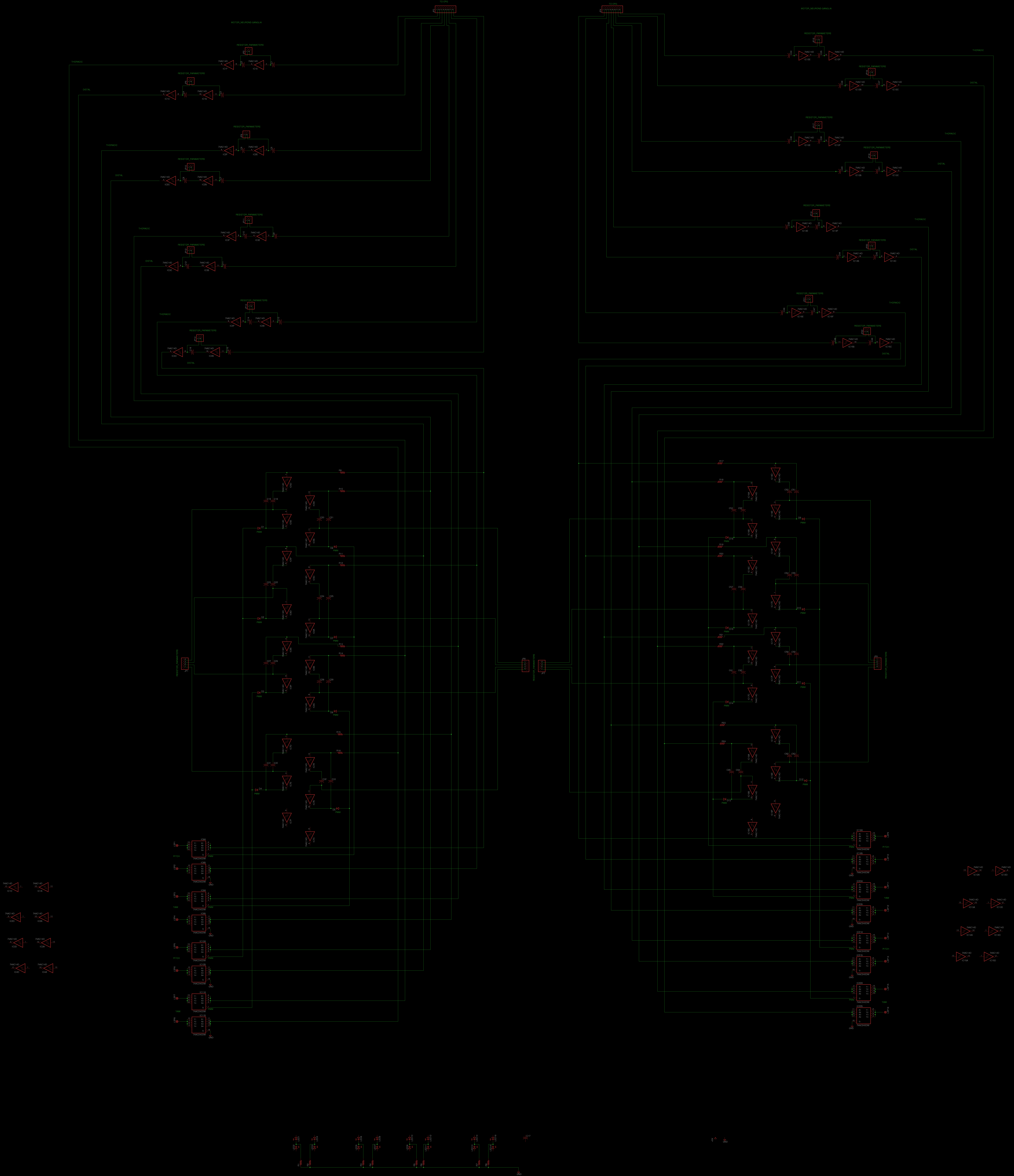
CIRCUIT DIAGRAMS

The Replica's motor driver is a nervous network based on the A-net over in the experiments/ | Topologies | page.
The Replica has a 2 motor A-net per leg. The circuit is Split in a RHS, LHS (right/left hand side) manner. Further, each side has 2 groups of Thoracic and Distal pathways controlling the motions of the replica's yaw and pitch motors respectively. In addition, there are several header pins labelled "Resistor Parameters". These lines control the arguments of the motor driver nervous network. Again, an explaination is on the Topologies page.

Motor Driver -
mtrdrvr_sch.png

Eagle Files: Schematics & Boards